Instructions and Parts List
OPERATING INSTRUCTIONS FOR FLO-MATIC DISPENSER
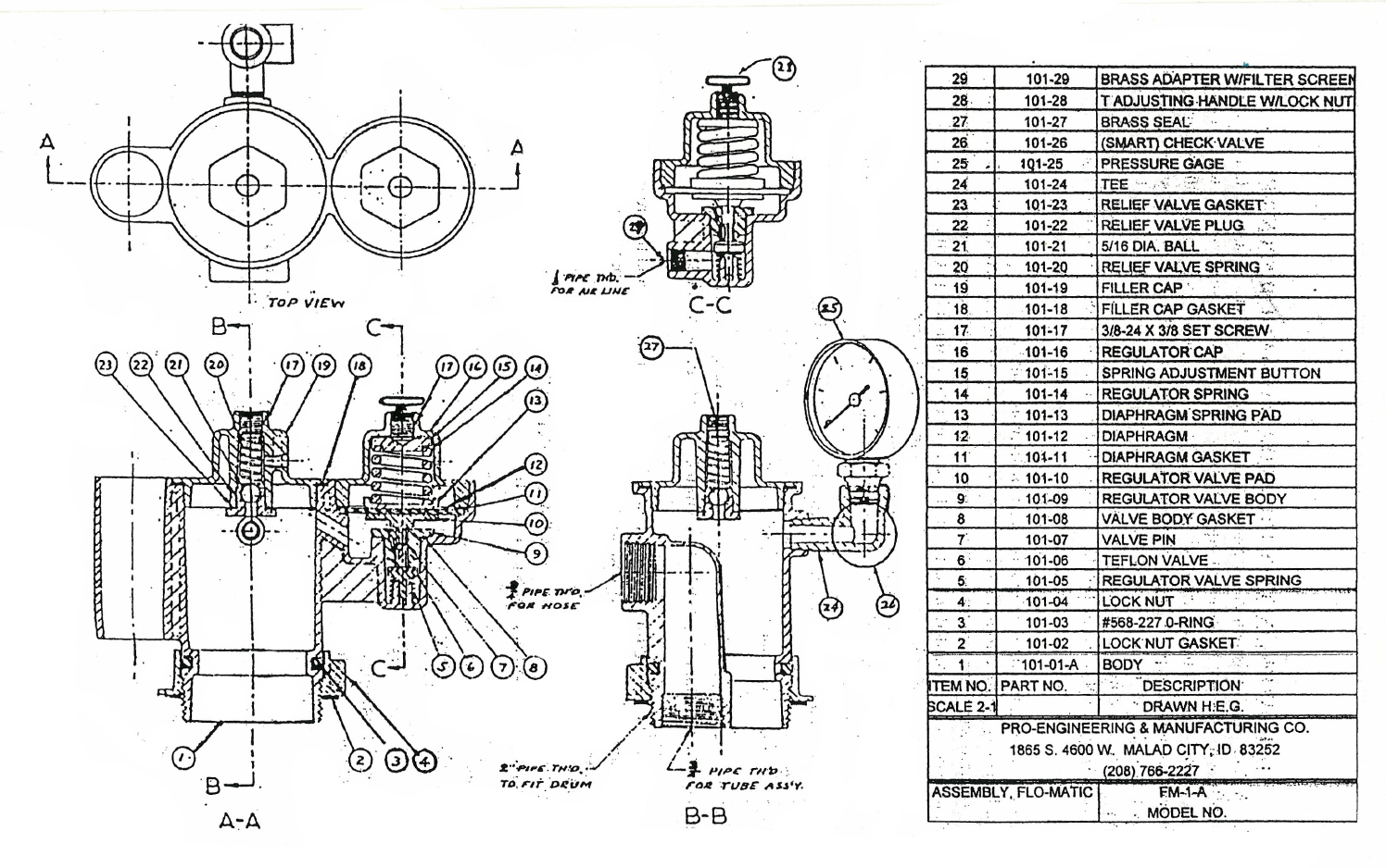
The FLO-MATIC liquid dispenser is designed to handle a wide variety of liquids. In most cases 6 psi is sufficient pressure for efficient liquid transfer. Therefore, the regulator is factory preset to operate from 0 to 6 psi regardless of air pressure applied to the dispenser. The safety relief valve is set to relieve at 8 psi, which well within the safety range of a 55 gallon drum of standard 18 gauge material. The regulator and relief valve can be adjusted to regulate rate of flow and for the moving of heavier and more viscous liquids than the 6 psi will efficiently handle. There is also a (Smart) check valve located on the T below the gauge, for a second safety feature.
ASSEMBLING THE DISPENSER
The use of pipe thread sealant will assist in an air-tight assembly.
1. Thread telescoping tube in bottom of dispenser. Extend tube to full length to insure reaching the bottom of container. Tube will telescope to proper length when dispenser is installed in drum.
2. Lock nut should be threaded up as far on dispenser body as threads permit.
3. Make sure gasket is in place between drum opening and lock nut.
4. Thread dispenser in drum as far as lock nut permits.
5. Back off enough to obtain dispenser position desired, then tighten lock nut securely against the drum opening.
6. Assemble hose and shut off nozzle (or drum faucet assembly) and thread into 3/4″ liquid outlet opening.
7. Connect air supply to intake port of pressure regulator.
To actuate the dispensing system, turn the regulator T handle clockwise to the desired pressure (indicated on the pressure gauge) which determines the rate of flow in GPM.
If pressure above factory setting is desired, hold lock nut with wrench ‘and turn regulator T handle clockwise. Adjust pressure slowly and observe gauge for indication of pressure in system. .
DO NOT INCREASE PRESSURE BEYOND LIMITATIONS OF THE (SMART) CHECK VALVE WHICH WILL RUPTURE AT APPROXIMATELY 11 psig. THEN RESETS ITSELF VHEN PRESSURE IS RELEASED.
If pressure above 8 psi is desired, the relief valve (located in filler cap, item # 19 on reverse side of this sheet) should be adjusted correspondingly.
RESETTING PRESSURE RELIEF VALVE
1. Remove seal from opening in top of filler cap.
2, Turn adjusting screw clockwise to increase popoff pressure, counterclockwise to decrease popoff pressure.
PRO-ENGINEERING & MANUFACTURING LLC.
PUMP DIVISION
Parts List Below Click For Larger View